In this simple tutorial I will show you how I transformed my normal bathroom door into a smart bathroom door to help with congestion.
Parts
- ESPHome framework
- ESP8266 (I use an Adafruit HUZZAH ESP8266)
- Active piezo buzzer
- Neopixel LED bar
- Magnetic door sensor
- 3D printed enclosure (optional)
Pictures
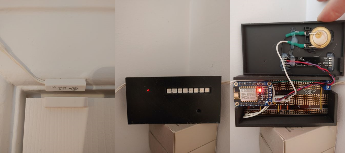
Context
First of all, let’s talk about ESPHome, this awesome project is basically a framework to build firmware for different ESP MCUs. You just have to provide a config file written in YAML and you are good to go without writing C code. It was my first time using it for this simple project but it was my fastest idea to working prototype ever.
The basic idea is the following, we are always between 6 to 8 people in my home and we only have one bathroom. So it happen quite often that you need to go but someone is already there so you have to wait behind the door. So I wanted to be able to see if the door was opened or closed remotely and for how much time. I also wanted to be able to send an alarm if the person in the bathroom was there for a suspicious amount of time.
So the solution was to use ESPHome to make the bathroom door “smart” and combine that with Home Assistant to make it easy to see the data from any computer or cellphone.
The MCU with ESPHome can work on its own but combining it with Home Assistant makes it far more user-friendly.
Code
You’ll see that the code is very basic with a couple of more complex snippets but ESPHome makes it really simple and the documentation on their site is really well made. Everything is declared in the YAML config file like little modules that can interact with each other.
That first block in the YAML config is very simple, you just have to set the right MCU you are using and your wifi informations. It is also strongly suggested to have an OTA update password, if not anybody that has access to your local network can push a firmware update from a web browser. NTP time syncing is also strongly suggested since I want to see the real date and time for each door events.
1
2
3
4
5
6
7
8
9
10
11
12
13
14
15
16
17
18
19
20
21
22
23
24
25
26
27
28
29
30
31
32
33
34
esphome:
  name: wifitoilet
  on_boot:
    - light.turn_on: status_l

esp8266:
  board: huzzah

# Enable logging
logger:

# Enable Home Assistant API
api:
  password: ""

ota:
  password: "****************"

wifi:
  ssid: "CanIGetA_OhYeah"
  password: "**************************"

  # Enable fallback hotspot (captive portal) in case wifi connection fails
  ap:
    ssid: "Wifitoilet Fallback Hotspot"
    password: "UMG9vSbYhkfu"

web_server:
  port: 80

  time:
  - platform: sntp
    id: sntp_time
    timezone: America/Toronto
So let’s get back to the main idea, making that bathroom door smart, I wanted to have the following features ;
- View the door state remotely
- View since when the door was closed
- Warn the person in the bathroom that someone is waiting
First I needed a way to tell the ESP if the door is opened or closed, for that I used a simple magnetic door sensor and connected it to a GPIO pin. As you can see below, I defined a binary sensor and I set the pin to 12. I also added a delay of 250ms to change between states to avoid reporting too fast to Home Assistant. I also named the sensor and set its device class.
1
2
3
4
5
6
7
8
9
10
11
12
binary_sensor:
  - platform: gpio
    pin:
      number: 12
      mode:
        input: true
        pullup: true
    filters:
      - delayed_on_off: 250ms
    id: toilet_door_sensor
    name: Toilet Door
    device_class: door
Now the only thing remaining is being able to warn a bathroom user that is taking a bit too much time. For this I used an active piezo buzzer and some addressable RGB LEDs, with this I have an audio and visual warning.
First thing I needed is a PWM output pin to play a tone with the piezo buzzer. I selected pin 14, defined it as ‘esp8266_pwm’ and set its id as ‘rtttl_out’. Then I defined a RTTTL object that use the previously configured ‘rtttl_out’.
Right after this, I defined the warning LEDs. I selected ‘neopixelbus’ because this is what I had on hand, there’s a lot of options in esphome so select what you prefer. I also need to tell esphome a couple details about the LEDs strip used, mine had 8 WS2812 LEDs on it and it’s controlled by pin 5 of the ESP. You can also see that I defined a simple custom light effect in the ‘effects’ section.
Now all I need is a software button to activate the buzzer and light. The button definition itself is pretty simple, all the magic happens in the ‘on_press’event. You can see that I first call ‘rtttl.play’ with a strange looking string, that string is actually the different tones and timings to play instead of just playing a single tone. You can find a lot of those on the web. Then using lambda calls to turn on the LEDs and perform the effect I defined earlier, do that effect for a 10 seconds delay and turn off the LEDs.
1
2
3
4
5
6
7
8
9
10
11
12
13
14
15
16
17
18
19
20
21
22
23
24
25
26
27
28
29
30
31
32
33
34
35
36
37
38
39
40
41
42
43
44
45
46
47
48
49
50
51
52
output:
  - platform: esp8266_pwm
    pin: 14
    id: rtttl_out

rtttl:
  output: rtttl_out
  on_finished_playback:
    - logger.log: 'Song ended.'

light:
  - platform: neopixelbus
    id: sos_light
    type: GRB
    variant: WS2812
    pin: 5
    num_leds: 8
    name: "SOS Light"
    internal: true
    effects:
      - strobe:
          name: "Poopoo-Alert"
          colors:
            - state: true
              brightness: 100%
              red: 100%
              green: 100%
              blue: 0%
              duration: 1000ms
            - state: false
              duration: 350ms
            - state: true
              brightness: 100%
              red: 100%
              green: 0%
              blue: 0%
              duration: 1000ms

button:
  - platform: template
    id: button_warning
    name: I need to go!
    on_press:
      - rtttl.play: "Looney:d=4,o=5,b=140:32p,c6,8f6,8e6,8d6,8c6,a.,8c6,8f6,8e6,8d6,8d#6,e.6,8e6,8e6,8c6,8d6,8c6,8e6,8c6,8d6,8a,8c6,8g,8a#,8a,8f"
      - lambda:
          auto call = id(sos_light).turn_on();
          call.set_effect("Poopoo-Alert");
          call.perform();
      - delay: 10s
      - lambda:
          auto call = id(sos_light).turn_off();
          call.perform();
There’s also a great little feature in esphome called ‘status_led’, you can basically use any LED through a simple GPIO to have a visual indicator of the health of the system. Super simple to configure and voila!
1
2
3
4
5
6
7
8
light:
  - platform: status_led
    name: "Status LED"
    pin:
      number: 0
      inverted: true
    id: status_l
    internal: true
I printed a small enclosure and power the device with a simple 5V wall adapter.
I hope this can help someone, feel free to ask questions or comments down below!
Thanks for reading ;-)