A lot of my projects can be battery powered so being able to make my own battery packs with 18650 cells is very handy. This project can be built for relatively cheap by using a microwave transformer and recycled power cables.
This kind of spot welder is super simple, the idea is to have the Arduino control the amount of time a relay will let the power go through a microwave transformer, creating a short pulse of high current that will create the weld.
In this first part, we will cover the wiring and code to control the timing of the relay.
Parts
- Arduino Nano (any Arduino will do)
- SSD1306 OLED display (I2C)
- SSR Relay
- Potentiometer
- Resistor
- Button
Connections
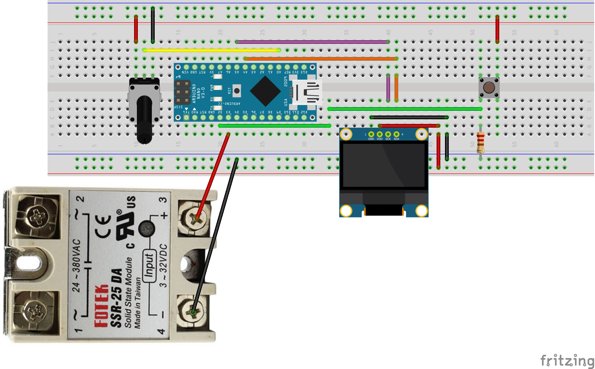
Code
First thing we need to configure is the U8glib library to be able to send information to the OLED display and some variables to select our pins and delays.
1
2
3
4
5
6
7
8
9
10
11
12
#include "U8glib.h"

U8GLIB_SSD1306_128X64 u8g(U8G_I2C_OPT_NONE | U8G_I2C_OPT_DEV_0);	// I2C

int potPin = 0;   // analog pin used to connect the potentiometer
int potVal;       // variable to read the value from the analog pin

int inPin = 2;
int triggerSwitch = 0;
int ssrPin = 3;
int stringWidth = 0;
unsigned long lastMs = 0;
Next, a simple little function that will manage all we need to write on the OLED display. The code is pretty self-explanatory, apart from maybe the u8g.setScale2x2() function that is used to display bigger characters.
1
2
3
4
5
6
7
8
9
10
void draw(void) {
  // graphic commands to redraw the complete screen
  u8g.setFont(u8g_font_unifont);
  u8g.drawStr( 12, 10, "YG Spot Welder"); // rename to personalise ;)
  u8g.setScale2x2();
  u8g.setPrintPos(20, 20);
  u8g.print(potVal);
  u8g.undoScale();
  u8g.drawStr( 20, 60, "Milliseconds");
}
Now, we need to complete Arduino’s setup function. Let’s skip over the triggerCallback() function for now and see the setup parameters.
I start the serial port and wait a bit to be sure that everything is ready to go then I set the color, intensity and pixel mode. I use a monochrome display so it basically makes the display write white on black at maximum intensity.
Then we set the button pin as an input and the relay pin as an output.
Lastly, we use the attachInterrupt() function to tie together the button and the triggerCallback() function meaning that each time the button is released (because I selected FALLING edge) the triggerCallback() function will execute.
1
2
3
4
5
6
7
8
9
10
11
12
13
14
15
16
17
18
19
20
21
22
23
24
void triggerCallback(void) {
  triggerSwitch = HIGH;
}

void setup(void) {
  Serial.begin(115200);

  delay(2500); //sanity wait

  if ( u8g.getMode() == U8G_MODE_R3G3B2 ) {
    u8g.setColorIndex(255);     // white
  }
  else if ( u8g.getMode() == U8G_MODE_GRAY2BIT ) {
    u8g.setColorIndex(3);         // max intensity
  }
  else if ( u8g.getMode() == U8G_MODE_BW ) {
    u8g.setColorIndex(1);         // pixel on
  }

  pinMode(inPin, INPUT);
  pinMode(ssrPin, OUTPUT);
  attachInterrupt(digitalPinToInterrupt(inPin), triggerCallback, FALLING);
  Serial.println(">>> MCU Ready <<<");
}
Now, let’s dive in Arduino’s loop function. We first notice that the display will get updated every 500ms by calling the draw() function. We also read the analog value of the potentiometer and map it to values from 10 to 750. It means that our pulse can vary from 10ms to 750ms.
Then we have the actual relay switching. We remember that the button release will activate an interrupt that will execute the triggerCallback() function and set the triggerSwitch variable to HIGH.
When triggerSwitch gets HIGH, the relay is closed to let current pass through it, we then leave the relay closed for the amount of milliseconds defined by the potVal variable. After this, we open the relay to stop the current flow.
I added a 1000ms delay before setting triggerSwitch LOW to avoid being able to make multiple pulse in a short amount of time because it might overheat the relay.
1
2
3
4
5
6
7
8
9
10
11
12
13
14
15
16
17
18
19
20
void loop(void) {
  if((millis() - lastMs) > 500) {
    // picture loop
    u8g.firstPage();
    do {
      draw();
    } while ( u8g.nextPage() );

    //Read pot value and map it
    potVal = analogRead(potPin);                // reads the value of the potentiometer (value between 0 and 1023)
    potVal = map(potVal, 0, 1023, 10, 750);     // scale it to use it get the right time (value between 10 and 750)
  }

  if (triggerSwitch == HIGH) {
    digitalWrite(ssrPin, HIGH);
    delay(potVal);
    digitalWrite(ssrPin, LOW);
    delay(1000);
    triggerSwitch = LOW;
  }
So that’s about it for the Arduino part of this project. In part 2, I will modify a microwave transformer and hook it up to the relay and do some testing!
» Complete code available on GitHub «
I hope this can help someone, feel free to ask questions or comments down below!
Thanks for reading ;-)